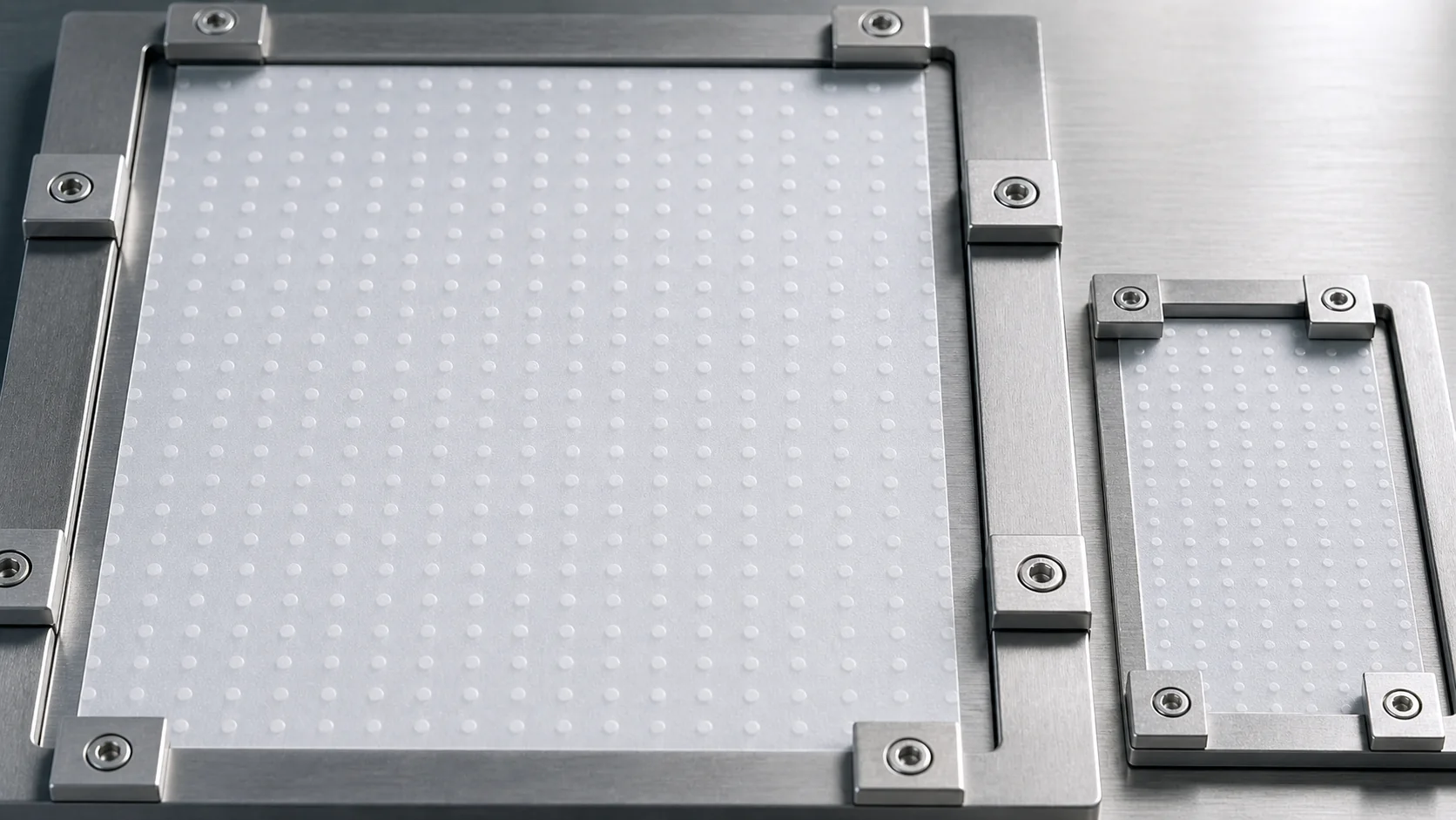
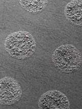
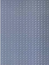
Controllable geometryDot diameter, spacing and coverage
Coating optionsWater/oil-based PVDF or PMMA
Key advantages.
Functional point-coating selection begins with the cell architecture, coating chemistry, dot geometry and process priorities.
Controllable dot diameter and spacing
Uniform impedance and stable interface
Strong adhesion for cell processing
Water/oil-based PVDF or PMMA options
SOURCE-DOCUMENTED PROFILE
Regular spot geometry, two documented application processes.
The supplied literature defines spot coating by uniform arrangement and controllable point diameter, spacing and coverage, then compares roller and array-spray application modes.
Technical content reproduced from the supplied spot-coated separator literature, pages 11–12.
01
Uniform coating with a regular spot arrangement
02
Controllable point diameter, spacing and coverage
03
Uniform impedance, stable interface and strong adhesion
APPLICATION PROCESSES
Roller dots and array spraying.
The source separates these methods by equipment, changeover, speed, impedance and film-flatness requirements.
A controlled array process with higher equipment and process requirements and greater flatness tolerance.
Higher equipment and process requirements
Electromechanical control and error prevention
Higher line speed
Lower impedance
Higher tolerance of film-surface flatness
PHYSICAL PROPERTIES
Spot-coated separator matrix
Four published constructions retain their original C/P structure codes. The supplied pages do not define those abbreviations, so no expanded meaning is added here.
Compare all 4 published configurations →
Test item
Dir.
5 μm base5+1C+1P
7 μm base7+1C+1P
9 μm base9+3C+2P
16 μm base16+2P
Finished thicknessμm
—
7±1
9±1
14±1.5
18±1.5
Air permeabilitysec/100 cc
—
180±40
180±40
200±40
220±40
Tensile strengthMPa
TD
≥140
≥140
≥120
≥140
Tensile strengthMPa
MD
≥140
≥140
≥120
≥160
Puncture strengthgf
—
≥500
≥450
≥500
≥600
Heat shrinkage105°C · %
TD
≤2
≤2
≤2
≤2
Heat shrinkage105°C · %
MD
≤2
≤2
≤2
≤2
Heat shrinkage130°C · %
TD
/
/
≤3
/
Heat shrinkage130°C · %
MD
/
/
≤3
/
Total PVDF coating weightg/m²
—
0.4±0.1
0.4±0.1
0.6±0.2
0.6±0.2
The “/” marks are reproduced from the source table; no missing 130°C value is inferred.
The source notes that spot-coating materials can include water-based PVDF, oil-based PVDF and PMMA.
QUALIFICATION CONTEXT
From literature value to qualified grade.
Published matrices support initial comparison. Final specifications remain tied to the selected grade, agreed test method and lot-specific quality documentation.
Application areas
Advanced lithium-ion cells
Energy storage
Industrial batteries
Get pricing for Spot Coated Separator.
Send the target thickness, width, coating requirements and volume for a project quotation, typically expressed in USD per square metre.